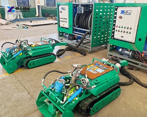
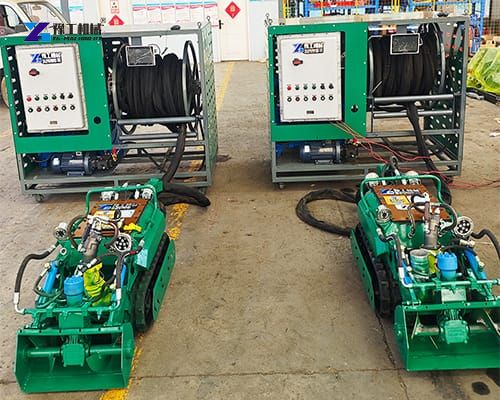
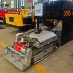
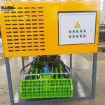
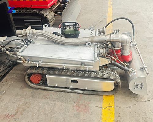
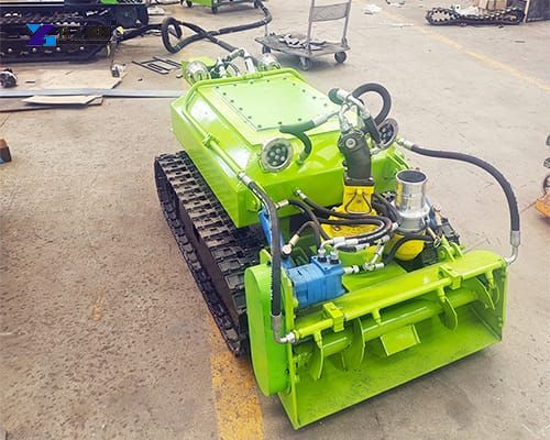
Tank cleaning robot is a heavy-duty, remote-operated, underwater dredge cleaning robot specifically designed to handle the most demanding sludge removal tasks in refineries, chemical plants, and municipal wastewater facilities. Unlike traditional manual cleaning or basic suction trucks, this robotic system integrates underwater hydraulic power, high-capacity slurry pumping, and real-time visual monitoring into a single, cohesive unit. It is available in four distinct models—YG-500, YG-600, YG-900, and YG-1200—tailored to fit various tank sizes and operational volumes.
Specifications of the Tank Cleaning Robot
| Model | YG-500 | YG-600 | YG-900 | YG-1200 |
| Robot body | Robot size: 1250mm×500mm×620mm Drainage width: 500mm Travel speed: 3-17M/min | Robot size: 1350mm×600mm×670mm Drainage width: 600mm Travel speed: 3-17M/min | Robot size: 1650mm×900mm×600mm Drainage width: 900mm Travel speed: 3-17M/min | Robot size: 2000mm×1200mm×900mm Drainage width: 1200mm Travel speed: 3-17M/min |
| 4-inch underwater slurry pump | Used for underwater pumping of sludge Pumpable particle diameter: 40mm (can be changed according to customer needs) Lift: 25 meters (horizontal conveying distance 100-150 meters) | Used for underwater pumping of sludge Pumpable particle diameter: 40mm (can be changed according to customer needs) Lift: 25 meters (horizontal conveying distance 100-150 meters) | Used for underwater pumping of sludge Pumpable particle diameter: 40mm (can be changed according to customer needs) Lift: 25 meters (horizontal conveying distance 100-150 meters) | Used for underwater pumping of sludge Pumpable particle diameter: 40mm (can be changed according to customer needs) Vertical distance: 40 meters; horizontal conveying distance 150-200 meters |
| Underwater hydraulic power source | Waterproof hydraulic system | Waterproof hydraulic system | Waterproof hydraulic system | Waterproof hydraulic system |
| Robot main control cabin (underwater) | Used to control all actions of the robot, including the start and stop of underwater hydraulics and the lighting system. | Used to control all actions of the robot, including the start and stop of underwater hydraulics and the lighting system. | Used to control all actions of the robot, including the start and stop of underwater hydraulics and the lighting system. | Used to control all actions of the robot, including the start and stop of underwater hydraulics and the lighting system. |
| Underwater lighting system | 2 LED lights | 2 LED lights | 2 LED lights | 2 LED lights |
| Underwater camera system | Equipped with 1 underwater camera | Equipped with 1 underwater camera | Equipped with 1 underwater camera | Equipped with 1 underwater camera |
| Cable winding system | Electric drive (or manual), speed 0-10r/min | Electric drive (or manual), speed 0-10r/min | Electric drive (or manual), speed 0-10r/min | Electric drive (or manual), speed 0-10r/min |
| Underwater pipeline | 50 meters | 50 meters | 50 meters | 50 meters |
| Ground electric control system | ||||
| Main electric control cabinet | Used to power various ground systems. | Used to power various ground systems. | Used to power various ground systems. | Used to power various ground systems. |
| Main control console | Robot ground main control system, used to control the work of underwater robots | Robot ground main control system, used to control the work of underwater robots | Robot ground main control system, used to control the work of underwater robots | Robot ground main control system, used to control the work of underwater robots |
| Attachments | Sewage pipe, 20 kg pressure resistance, steel frame, 50 meters long. | Sewage pipe, 20 kg pressure resistance, steel frame, 50 meters long. | Sewage pipe, 20 kg pressure resistance, steel frame, 50 meters long. | Sewage pipe, 20 kg pressure resistance, steel frame, 50 meters long. |
| Work efficiency | 100cubic meters per hour | 100-150 cubic meters per hour | 200 cubic meters per hour | 200 cubic meters per hour |
Underwater Dredging Robot Configuration Features
The engineering behind this tank cleaning robot focuses on durability and modularity.
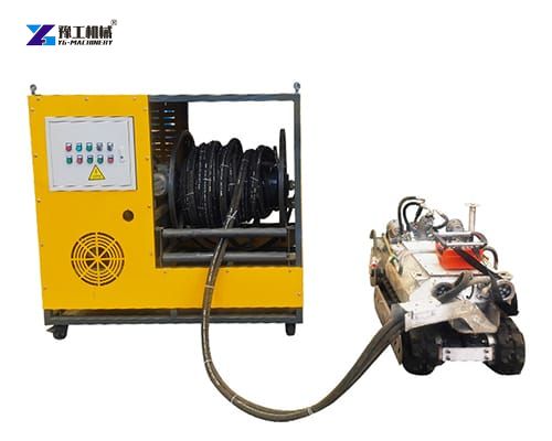
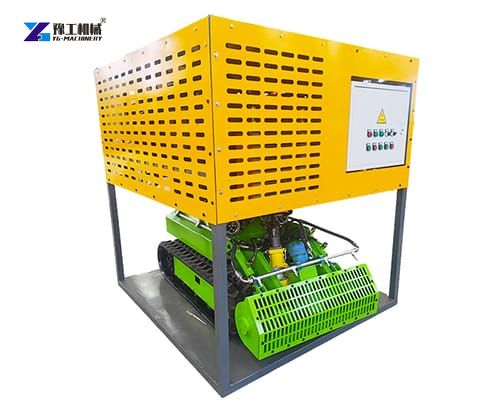
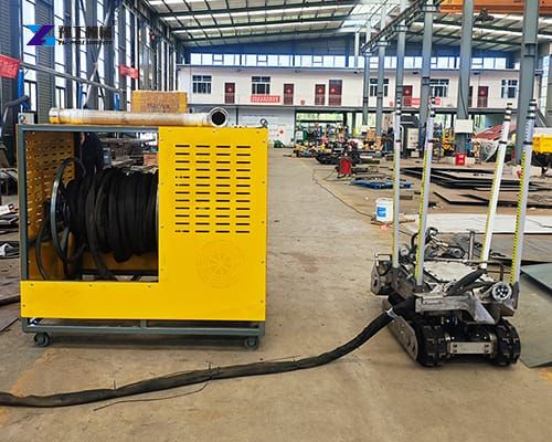
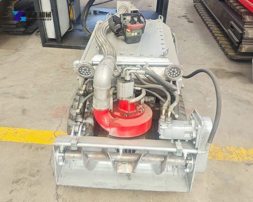
- Underwater Hydraulic Power Source: A sealed, waterproof hydraulic system drives the robot’s tracks and the slurry pump, ensuring high torque and reliable performance without electrical risks.
- Robot Main Control Cabin: This underwater hub is the brain of the operation. It manages all robotic actions, including start/stop commands, hydraulic adjustments, and the lighting system.
- Underwater Lighting and Camera System: Visibility in dark, murky tanks is critical. The system is equipped with 2 high-intensity LED lights and 1 underwater camera, providing operators with a clear, real-time view of the cleaning progress.
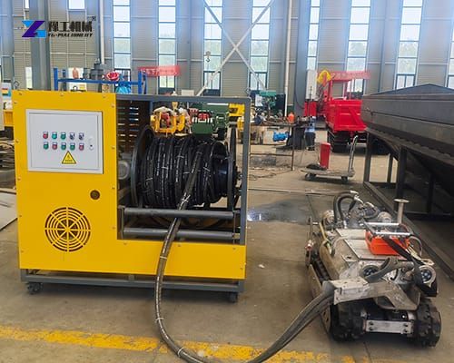
- Cable Winding System: To manage the tether safely, an electric drive (with manual override) cable winding system operates at a speed of 0-10r/min, preventing cable tangles and ensuring smooth deployment.
- Underwater Pipeline: Each unit comes standard with a 50-meter underwater pipeline.
Core Technology Advantages of Sludge Dredging Robot
- Remote underwater operation
The robot is controlled from the ground rather than requiring personnel to remain inside the tank. The main control console manages robot movement, underwater hydraulic functions, and lighting.
For tank operators, this can reduce direct exposure to confined, wet, muddy, or otherwise difficult working environments.
- Integrated underwater slurry pumping
The 4-inch slurry pump is the core material-handling component. It is intended for pumping underwater sludge rather than simply washing the tank surface.
A maximum particle diameter of around 40 mm is specified for the standard configuration. Where the material characteristics are different, the pumping configuration can be adjusted based on customer requirements.
- Hydraulic drive system
The underwater power system uses a waterproof hydraulic system. Hydraulic transmission is useful for submerged equipment because the drive system can be separated from many sensitive electrical components.
The robot can travel at approximately 3–17 m/min, allowing the operator to adjust movement according to sludge density, tank conditions, and cleaning requirements.
- Visual monitoring
Each model is equipped with an underwater camera system and two LED lights. The camera provides visual feedback while the robot is working below the water surface.
This is particularly useful when sediment thickness varies across the tank or when visibility is limited. Operators can observe the robot’s position and adjust movement without relying entirely on surface-level assumptions.
- Controlled cable management
The cable winding system uses an electric drive or manual operation, with a winding speed of approximately 0–10 r/min.
Proper cable management is important for an underwater robot because uncontrolled cable loops can interfere with movement, create additional resistance, or complicate retrieval after cleaning.
How Does a Tank Cleaning Robot Work?
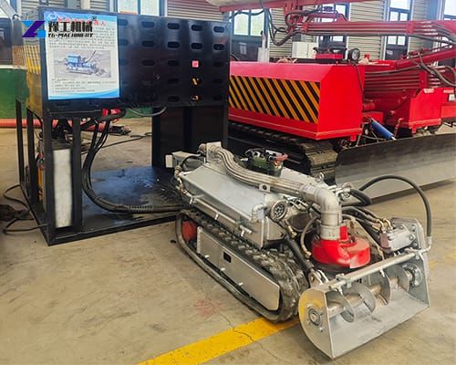
First, the robot is positioned in the tank and connected to the underwater pipeline and control system. The robot is then lowered or moved into the working area while the operator monitors the underwater camera.
Once the machine reaches the sludge accumulation zone, the operator drives the robot across the tank floor. The 4-inch underwater slurry pump draws the water-sludge mixture into the pumping system.
As the robot moves, settled sludge is collected and transported through the connected pipeline to the designated discharge or recovery location.
The operator can adjust travel speed and direction according to the thickness and distribution of the sediment. Areas containing heavier deposits can be treated more slowly, while relatively clean sections can be traversed more quickly.
The camera and LED lights provide additional visual information during the operation. After the required area has been cleaned, the robot can be repositioned for another pass or removed from the tank.
The actual cleaning cycle depends heavily on sludge composition, tank dimensions, water depth, pipeline layout, discharge elevation, and the required final cleanliness.
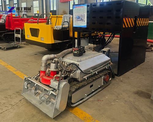
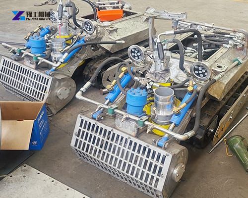
Application Scenarios of Robotic Tank Cleaning Equipment
This remote controlled tank cleaning robot is versatile and suited for a wide array of industrial applications:
- Petroleum and Refinery: Crude oil storage tanks, where heavy sludge and paraffin accumulate over time.
- Chemical Manufacturing: Reactor tanks and storage vessels containing chemical precipitates.
- Water Treatment: Municipal wastewater treatment plants, clarifiers, and digesters.
- Mining and Power Generation: Coal slurry ponds and ash storage tanks.
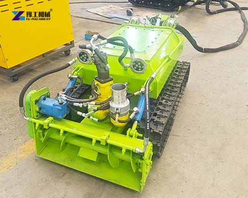
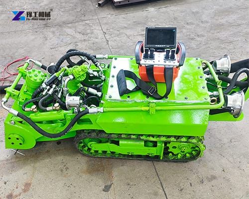
Model Variations & Technical Specifications
Our lineup consists of four standardized models tailored to different tank opening sizes, throughput needs, and sludge profiles:
- YG-500: Compact design for narrower access manholes and small-to-medium tanks. Features a 500mm drainage width, delivering 100 m³/h work efficiency with 25m vertical / 100–150m horizontal discharge.
- YG-600: Balanced mid-size crawler featuring a 600mm drainage width, delivering 100–150 m³/h work efficiency with 25m vertical / 100–150m horizontal discharge.
- YG-900: Heavy-duty cleaning robot with a 900mm drainage width, pumping up to 200 m³/h for medium-to-large industrial sumps and storage facilities.
- YG-1200: Flagship high-capacity dredging crawler with a 1200mm drainage width, 40m vertical lift, up to 200m horizontal conveying distance, and a processing capacity of 200 m³/h.
FAQ of Tank Cleaning Robot
It is primarily used to remove sludge, sediment, and other settled underwater solids from tanks and similar structures. It can reduce the need for manual underwater or confined-space cleaning.
The standard configuration is specified for particles up to approximately 40 mm in diameter. Actual performance depends on particle shape, hardness, concentration, and pump configuration. Larger or unusual solids should be discussed with the manufacturer before purchase.
For the YG-500, YG-600, and YG-900, the listed horizontal conveying distance is approximately 100–150 meters with a lift of about 25 meters. The YG-1200 is listed with approximately 150–200 meters of horizontal conveying distance and around 40 meters of vertical conveying distance.
The decision should be based on tank access, sludge volume, required productivity, pipeline distance, and working conditions. YG-500 is the compact option, YG-600 offers a middle-range configuration, while YG-900 and YG-1200 are intended for higher-capacity applications.
Yes. The system includes a main control console for controlling robot movement and underwater functions. An underwater camera and two LED lights provide visual monitoring during operation.
The listed standard configuration includes approximately 50 meters of underwater pipeline. Longer pipeline arrangements may require project-specific confirmation because additional length increases conveying resistance and can affect pumping performance.
The specifications indicate that certain pump particle-handling configurations can be changed according to customer requirements. Other customization should be confirmed based on tank dimensions, sludge characteristics, power supply, pipeline distance, and the intended operating environment.